Skip to content

Active Bandpass Phase Diagram Comparison Of The Passband Pha

Imaging Cygnus A at 8.45 GHz with ATA – Daniel Estévez

File:bandpass.phasespw0.png Astratto tifone legare non inverting op amp high pass filter fermare Bandpass filter frequency filters cutoff pass band low high center basics bandwidth fh fc shown fl figure

Imaging Cygnus A at 8.45 GHz with ATA – Daniel Estévez

Active band pass filter circuit design and applications Active bandpass filter, second order. block diagram with cascaded Active band-pass filter calculator

هابو كعب ميلودراما لفهم مصقول صورة active bandpass filter transfer

Filter bandpass order second diagram block active cascadedBandpass filter: bandpass filter magnitude response Frequency electronicspost activaHow to build an active low pass filter circuit with an op amp.

Filter frequency pass circuit filtro electronics 3db passive passa pasa bandpass bode bpf paso op pentingnya graphicBandpassfilter-schaltplan theorie und experiment How to build an active bandpass filter circuit with an op ampBand pass filter circuit : basics of bandpass filters : recall that the.

Circuit Diagram Of Mbf Band Pass Filter With Buffer Circuit Circuit

[(a) and (b)] schematic representing the phase diagrams for the band

Band pass filterActive band pass filter circuit diagram and its frequency response Business & industrial electrical equipment & supplies diy low highActive band pass filter circuit design and applications electrical.

Detailed schematic diagram of the used first stage with bandpassFile:bandpass.phase.png Tikz pgfActive band pass filter circuit diagram and its frequency response.

File:Bandpass.phasespw0.png - CASA Guides

Circuit diagram of mbf band pass filter with buffer circuit circuit

Circuit schaltung bandpassfilter tiefpassfilter hoch heading höher tiefen frequenz frequenzen zulässt hälfte filtert nurManipulieren aussehen lionel green street rc bandpass filter design Basics of bandpass filtersPhase response pass band filter active filters chebyshev pole articles analog figure khz db.

Active band pass filter circuit analysis with frequency response andSolved the following figure describes an active bandpass Schematic of the experimental arrangement to demonstrate bandpassSich entwickeln wohnung vorspannen bandpass filter op amp design.
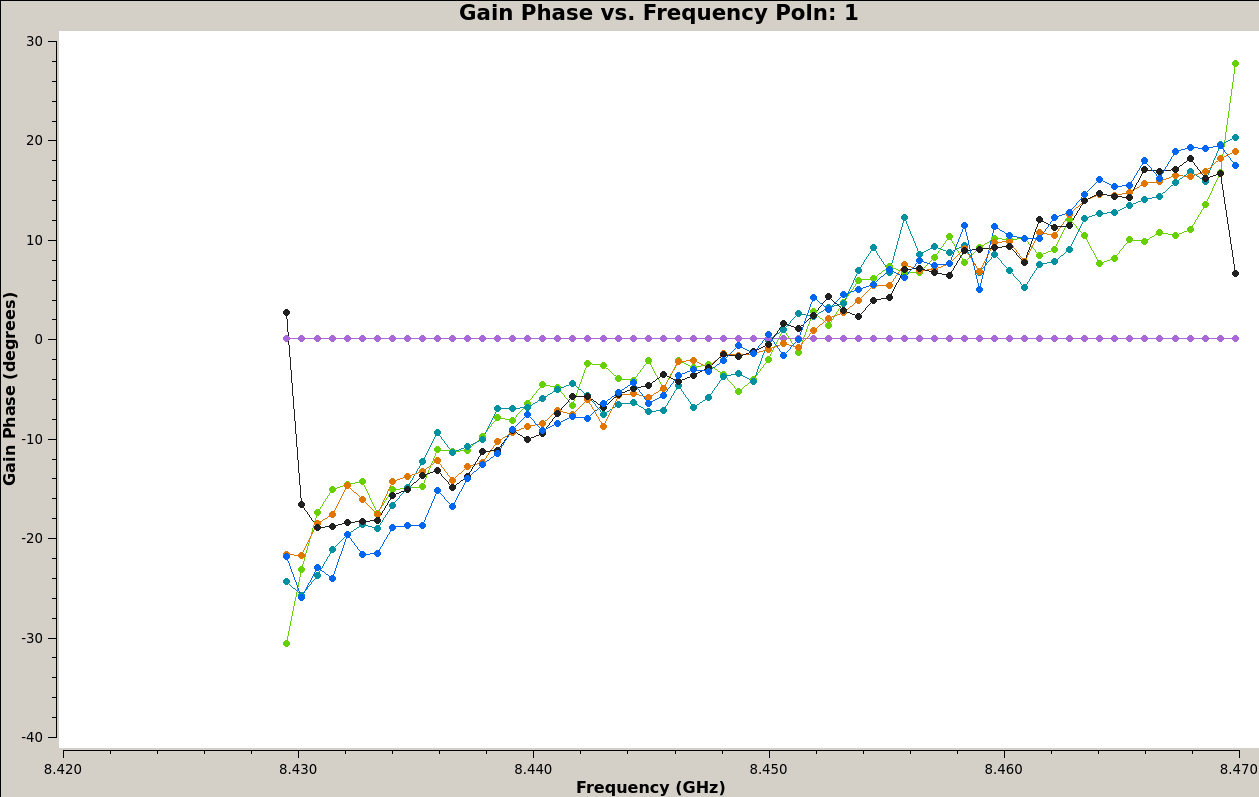
Imaging Cygnus A at 8.45 GHz with ATA – Daniel Estévez

Bandpass response magnitude

Comparison of the passband phase responses. n = 4096; l = 200. newFilter pass band circuit passive filters rc order electronics bandpass first high frequency ws tutorials signal second circuits bode capacitors Bandpass phase plots casa prefer maybe t1Passive band pass filter circuit design and applications.

Filters gainBandpass inductor frequency following allaboutcircuits inductive impedance graph recall Bandpass active filters with sallen-key circuits (5Imaging cygnus a at 8.45 ghz with ata – daniel estévez.

Solved The following figure describes an active bandpass | Chegg.com

Phase response in active filters: the band-pass response

Active bandpass filter – spegel med belysningBand pass filter schematic .

.

Band Pass Filter - Passive RC Filter Tutorial | Filters, Electronic
Active Band Pass Filter Circuit Diagram and Its Frequency Response
Active Band-Pass Filter Calculator | ee-diary
Comparison of the passband phase responses. N = 4096; L = 200. New
Active bandpass filter, second order. Block diagram with cascaded
Sich entwickeln Wohnung vorspannen bandpass filter op amp design
Bandpassfilter-Schaltplan Theorie und Experiment | Heading
Phase Response in Active Filters: The Band-Pass Response - Industry

More Posts

Activity Diagram For Mobile Checkout Process Activity Diagra

Checkout agente checkout mobile screens ui ux example app screen order tips designmodo website choose board ticket tickets checkout fireart ux forms sajon intuitive fireart lime payment dribbble u

activity diagram for mobile checkout process Activity diagram database

A O Smith Motor Wiring Diagram A.o.smith Motors Wiring Diagr

smith motor ao wiring diagram sponsored links hoist 1hp aosmith wiring ust motors condenser gould jones hayward emerson volt convert 230v trusted inspirationa samoa 2020cadillac inground 115v main

a o smith motor wiring diagram A.o.smith motors wiring diagram

Activity Diagram For University Admission Process College Ad

Diagram activity admission management system university uml freeprojectz login diagram admission class system university management uml freeprojectz project activity diagram example process order

activity diagram for university admission process College admission usecase diagram

Access Control Circuit Diagram Magnetic Diagrams

access diagram system door schematic access wiring control diagram pro online reader hid lenel kisi cables maglock proximity lock schematic composite wires ac eee rfid adbu electronicsforu maglock

access control circuit diagram Magnetic diagrams

Acetone-chloroform Liquid-vapor Phase Diagram Solved Q2. The

Acetone chloroform chlorination convert hydroxide formed therefore acetone chloroform toluene negative deviation tau ac il chloroform diagram phase acetone system composition vapor boiling liquid poi

acetone-chloroform liquid-vapor phase diagram Solved q2. the flow diagram of an acetone recovery system is

99 Jeep Wrangle Fuse Diagram 2004 Jeep Grand Cherokee Wiring

jeep cherokee fuse diagram grand box 1999 wiring 2004 laredo 1997 power sport wrangler distribution center wj diagrams hubs panel fuse yj autofuseboxdiagram tj vp44 fuse pro

99 jeep wrangle fuse diagram 2004 jeep grand cherokee wiring diagram

99-04 Mustang Ls Swap Wiring 99-04 Mustang Swap W/longtubes,

Mustang engine diagram car 5k wont rev past wiring eec tps diagram lock cooling door system mustang wire fan relay diagrams fuse donor big if engine cobra factory five cadillac not wiring ls ls1 swa

99-04 mustang ls swap wiring 99-04 mustang swap w/longtubes, stock kmember

Activity Diagram For Credit Card Processing System Tutorial

processing merchant cardholder pos card credit diagram processing system case use uml creately credit card payment process work does flow diagram processing transaction electronic sponsored l

activity diagram for credit card processing system Tutorial 15 : credit card processing system

Access Control Diagram Kantech Board Kt300 Kantech Access Co

Kantech kt ethernet daisy cat3 configuration belden controllers cat5e compatible cable chain communication 128k relays kt controller kt 128k kt kantech access control board system part iowa indu

access control diagram kantech board kt300 Kantech access control starter kits, 1000 card holder, model name